|
Technical Description
Beamline 11-BM is located on a APS bending magnet (BM) source operating at an electron energy of 7 GeV with a critical photon energy of 19.5 keV. The beamline currently operates over the energy range 15 keV - 35 keV.
The initial hutch houses the beamline optics, including a collimating mirror with Si and Pt stripes, a 20 mm offset fixed-exit double-crystal Si (111) monochromator (27.6 m from the source), and a 1 meter vertical focusing mirror. The second monochromator crystal is sagittally bent for horizontal focusing.
The main experimental hutch is located ~ 50 m from the source, at the center of which is a Huber two-circle diffractometer mounted on a large optical table. The table also serves as a base for sample environmental devices, the robotic sample arm used for unattended operation, and other accessories.
The diffractometer has a unique multi-analyzer detection assembly, consisting of 12 independent Si (111) crystal analyzers and LaCl3 scintillation detectors. This enables simultaneous high-speed (~1 hour) and high-resolution (ΔQ/Q ≈ 1.4×10⁻⁴) data collection.
|
11-BM Technical Description Links
|
|
Summary of 11-BM Technical Specifications
Source |
Bending Magnet (BM), Critical Energy = 19.5 keV |
Energy Range |
15 - 35 keV (λ ≈ 1.0 - 0.34 Å) |
Flux |
~ 5×10¹¹ phs/sec @ 30 keV |
Monochromator |
Si(111) double crystal (bounce up geometry) |
Focusing |
Sagittally Bent Si(111) Crystal (Horz), 1 meter Si/Pt mirror (Vert) |
Beam Size |
1.5 mm (horizontal) x 0.5 mm (vertical) focused at sample |
Detection System |
12 independent analyzer sets with 2θ seperation of ~ 2°
Si(111) analyzer crystals and LaCl3 scintillation detectors |
Angular Coverage |
2θ range: 0.5° - 130° at ambient temp (Qmax≈ 28 Å-1 at 30 keV) |
Resolution |
ΔQ/Q ≈ 1.4×10⁻⁴ (min. 2θ step size = 0.0001°) |
Capacity |
Automated robotic sample changer enables unattended
collection of 100+ individual samples |
Controls |
EPICS, MEDM, Python, PHP/MySQL |
|
Oxford Cryostream 700+ N 2 gas blower (100 - 450 K)
Cyberstar Hot Gas Blower (Ambient to 1000 °C)
Oxford Helium Cryostat (closed flow system) (Ambient to ~ 5 K)
In-Situ Reaction Cell and gas flow lines
more on the way, please send us your suggestions
Have a custom sample environment? Ask staff for details...
|
See the 11-BM Wiki for more information on specific sample environments
Publications & Presentations about 11-BM:
Published Journal Articles:
» General Beamline Overview:
Wang, J., et al, (2008) Review of Scientific Instruments v 79, p 085105
download reprint directly thanks to a generous AIP policy
» Multi-crystal analyzer detection assembly:
Lee, P. L., et al, (2008) Journal of Synchrotron Radiation, v 15, p 427
» Software for high-throughput management of 11-BM metadata:
Toby, B.H. et al. (2009) Journal of Applied Crystallography, v 42, p 990
Presentations & Posters :
» Introduction to 11-BM; 12 slide presentation
(April 2010; ~8 Mb PDF document)
» Single overview slide for 11-BM instrument
(April 2010; ~1 Mb PDF document)
» Poster describing 11-BM and Mail-In Service
(April 2010; ~10 Mb PDF document)
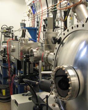
11-BM Beamline Layout:
The beamline consists of two hutches; an initial optics enclosure housing components used to shape and focus the beam, and an experimental end station dedicated to powder diffraction experiments. There is also a mini-hutch attached to the end station, which contains monochromatic beam slits and vacuum equipment for the beam transport tube. The beamline layout and main components are displayed in the figures below.
White beam slits define the beam entering the first optics hutch. A water-cooled Pt coated mirror located 26 m downstream from the bending magnetic source collimates the beam vertically. Following the first mirror, the beam is monochromated by a 20 mm offset fixed-exit double-crystal Si (111) monochromator. The water-cooled first crystal is flat, while the second crystal is sagittally bent to focus the beam horizontally. There are also four independent adjustment motions that are used to position the second crystal and assist focusing. A second mirror downstream of the monochromator, with selectable Si or Pt stripe coatings, is used for vertical beam focusing and harmonic rejection.
A large Huber two-circle diffractometer with high accuracy (~3×10⁻⁴°) and high precision (< 5×10⁻⁵°) is located in the experimental hutch. Several goniometer mounts are available for the diffractometer; the standard mail-in mount incorporates three-axis of translation motion and a high speed (> 90 Hz) sample spinner. The diffractometer, beam guard slits, a beam stop, and ion chamber are all mounted on an optical table that can be moved with respect to the x-ray beam. The optical table also supports sample environmental devices and a robotic sample exchanger. The unique 11-BM robotic sample changer is integrated into beamline controls and software, and permits automated high-throughput data collection of > 100 individual samples.
In order to achieve the goals of both high resolution and high-throughput in a powder instrument, a unique multi-analyzer detector system has been designed for 11-BM. The 12-analyzer detector system combines independent Si (111) crystal analyzers with LaCl3 scintillation detectors. Each crystal has individual θ and χ adjustments. The analyzers are spaced 2° apart, so that a 2° scan covers a 24° 2θ range. A pair of slits between the sample and each crystal is used to separate and collimate the diffracted beam from the sample. This multianalyzer/detector scheme enables simultaneous high-speed (~1 hour) and high-resolution (ΔQ/Q ≈ 2×10⁻⁴) data collection.
11-BM Performance:
The 11-BM beamline couples an efficient sagittally focused x-ray beam with a high precision diffractometer circle and perfect Si(111) crystal analyzer detection to achieve world class sensitivity and resolution. Instrumental resolution at high Q is better than ΔQ/Q ≈ 2×10⁻⁴, with a typical 2θ resolution of < 0.01° at 30 keV. The figures below illustrate 11-BM performance and resolution capabilities.
Under ambient conditions the 12-analyzer detector system offers full coverage of the 2&theta from 0.5° - 130°, with partial detector coverage extending an additional 22° in both directions. The beamline Qmax is ~ 28 Å-1 at 30 keV (equivalent to ~ 0.25 Å), although a typical 1 hour mail-in scan extends to Q ≈ 12 Å-1 The minimum diffractometer 2θ step size is 0.0001°, and a scan may contain up to 160,000 steps (12 intensity and 2 monitors values recorded at each step). Data are collected 'on the fly', which enables considerably faster scans than a traditional step scan mode.
The x-ray beam size at the sample is ~ 1.5 mm (horizontal) x 0.5 mm (vertical). This tightly focused beam efficiently utilizes the bending magnet source (and is advantageous for studying microgram sized samples) and minimizes asymmetric diffraction peak broadening from axial divergence even at low angles.
Example powder diffraction data sets collected at 11-BM on standard reference materials are available to downloaded here.
Project History:
The concept for 11-BM originated as a DOE-BES LAB-03 instrument construction grant proposal written in 2003 by J.F. Mitchell, J.D. Jorgensen, R.B. Von Dreele, P.L. Lee, and M.A. Beno. This proposal successfully demonstrated the need for a dedicated high-resolution powder diffraction beamline at the APS.
Beamline construction commenced in early 2005 with 'first beam' occurring in the fall of 2007. After several months of commissioning and software development lead by Brian Toby, the mail-in user program was launched in the summer of 2008. 11-BM began accepting user proposals for on-site experiments starting with the 2009-3 run cycle.
The goal of 11-BM is to provide a user-friendly, high-resolution, high-throughput instrument with state-of-the-art powder diffraction capabilities to the scientifically diverse APS user community.
Acknowledgements:
The hard work of all those at the APS who shared in the design, construction and commissioning of 11-BM is most appreciated, most especially Matthew Suchomel, Brian Toby, Robert Von Dreele, Mohan Ramanathan, Yeldez Amer, Deming Shu, Jun Wang, Peter Lee, Sytle Antao, Jennifer Doebbler, Charles Kurtz, Mark Engbretson, Curt Preissner, Rogelio Ranay, Xuesong Jiao, David Cline, Tim Mooney, Yu Huang, Bill Sheehan, Dave Cyl, Mark Beno, Gabrielle Long, and George Srajer.
We also thank John Mitchell & the late James Jorgenson (Argonne/MSD) as well as Helen Kerch (BES/DOE) for their work. The instrument construction project was supported by the US Department of Energy, Office of Science, Office of Basic Energy Sciences, as part of DOE-BES LAB-03 instrument construction program. Used of the Advanced Photon Source was supported by the US Department of Energy, Office of Science, Office of Basic Energy Sciences, under contract No. DE-AC02-06CH11357.
|

 11-BM Home